






• 1.jpg
  • 2.jpg
  • 3.jpg
  • 4.jpg
  • 5.jpg
  • 6.jpg
  • 7.jpg
  • 042A8449-LowRes.jpg
  • inclusive-climbing.jpg
  • JULY-24-071.jpg
  • JULY-24-079.jpg
  • RVR_zipline-06.jpg
◆ Zipline Safety · Whitepaper

Zipline braking dynamics: brake systems, arrival speed and g-forces

Stopping a rider at the end of a zipline is a question of physics. Above about 10 km/h (6 mph), the energy a rider carries into the landing zone is high enough to cause serious injury if the brake does not work. This whitepaper explains what a complete zipline braking system is, what arrival speeds really mean, which g-forces riders feel during braking and how to test both brakes.

Short answerA zipline braking system is a primary brake and an independent emergency arrest device (EAD) that work together. The primary brake stops every rider smoothly; the EAD stops the rider automatically, without any input from rider or guide, if the primary brake fails. Both are designed for the full range of rider weights and arrival speeds, and both are tested before the line opens.
Zipline brakingEmergency arrest deviceASTM / ACCT
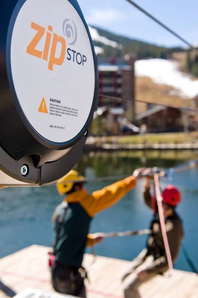
Magnetic zipline end brake at a landing platform with a guide receiving a rider
The standards

What is a zipline braking system?

The Association for Challenge Course Technology (ACCT) and ASTM International both publish standards for ziplines and their brakes. They are US standards, but widely used as references worldwide. In Europe, ziplines are designed to EN 15567 (European Ropes Course Standard). All of them come to the same point: one brake is not enough when a failure could hurt someone.

ACCT definitions

  • Brake system: an arrangement of primary and emergency brakes designed to function together to arrest the motion of a person.
  • Emergency brake: a brake on a zip line that engages without any participant input when the primary brake fails, in order to prevent serious injury or death.

The ACCT standards ask that the brake system is designed for the level of risk a failure of the system, or any of its parts, poses to the participant — including pinching, binding and entanglement. A qualified person tests the system at the extremes of the design range for participant weight and arrival speed.

ASTM definitions (F2291 and F2959)

  • Brake system: on aerial adventure courses this includes longitudinal friction brakes, disc or drum brakes and motor end brakes, on or off the rider-carrying device. If a brake failure leads to an unsafe condition, the brake system must be fail-safe.
  • Fail-safe: designed so that the normal and expected failure mode results in a safe condition.

ASTM also requires the designer or engineer to document a ride analysis that shows how hazards to people are managed, including a failure analysis such as a Fault Tree Analysis or a Failure Mode and Effects Analysis (FMEA).

A primary brake can be very reliable and still fail — through a third-party part, an installation or maintenance error, or simply wear and damage. That is why an emergency arrest device is part of the system, not an optional extra.
Arrival speed

How fast is too fast? Arrival speeds compared

Ziplines are built to be exciting, and exciting usually means fast. According to the manufacturer, the zipSTOP IR magnetic end brake accepts arrival speeds of up to 60 km/h (37 mph). What does such a speed mean for the rider when something goes wrong?

Arrival speed as a free fall

A useful way to understand arrival speed is to compare it with a fall. Gravity accelerates a falling body at 9.81 m/s², so the fall height that gives the same speed is h = v² / (2 × 9.81).

Arrival speedIn m/sEquivalent free fall
20 km/h (12 mph)5.6 m/s1.6 m (5 ft)
30 km/h (19 mph)8.3 m/s3.5 m (12 ft)
40 km/h (25 mph)11.1 m/s6.3 m (21 ft) — about two storeys
50 km/h (31 mph)13.9 m/s9.8 m (32 ft)
60 km/h (37 mph)16.7 m/s14.2 m (47 ft) — almost five storeys

A rider arriving at 60 km/h (37 mph) carries the same speed as someone who has fallen 14 m. Nobody would jump from a five-storey building without a complete safety system — and a fast zipline needs one too. Even a typical arrival speed of about 40 km/h (25 mph) equals a fall of more than 6 m (20 ft).

NASA chart of human tolerance to impact velocities with zones of certain and marginal survival

Figure 1 — Survival zones for impacts on a hard, flat surface at different vertical and horizontal velocities, from the NASA study Human Tolerance to Impact Velocities.

The NASA chart shows that a vertical impact at 16.7 m/s (55 ft/s) — the speed of a 60 km/h arrival — lies in the zone of marginal survival. The arrival of a 40 km/h rider sits near the transition from certain to marginal survival. Note that even the "certain survival" zone carries a real chance of serious injury: it is not an acceptable outcome.

Chart of arrival velocity in metres per second against equivalent free fall height in metres

Figure 2 — Arrival velocity (m/s) against the equivalent free-fall height (m).

Chart of arrival velocity in miles per hour against equivalent free fall height in feet

Figure 3 — The same in imperial units: a rider at 30 mph has the speed of a 30 ft fall.

Why guide-operated emergency brakes are not recommended

Many operators send a guide down first to receive guests at the landing. If that guide is also the emergency brake, who is the guide's emergency brake? Guides ride the line far more often than guests, so if a primary brake ever fails, the person most likely to be on the line is a guide. They deserve the same protection as paying riders.

A manual backup such as a prusik knot depends on a person reacting in time, and on the brake being reset correctly every time. Human error is exactly what an emergency brake should protect against.

The reaction-time problemAccording to the manufacturer, the zipSTOP IR has a maximum braking distance of 20 m (65 ft). A rider arriving at 60 km/h covers that distance in about 1.2 seconds. A single blink of the eye takes up to about 0.4 seconds — so a guide would have the time of three blinks to see the failure and activate a brake. An EAD must engage automatically.
Forces on the rider

G-forces during zipline braking

Whether a rider is injured during braking depends on many factors: what stops them, their body position, the hardware. One number explains a lot, though: the g-load.

G-load is the perceived weight a rider feels during deceleration. Standing still, you feel 1 g: your own body weight. The shorter the distance in which a rider is stopped, the higher the g-load. With constant deceleration it follows from g-load = v² / (2 × 9.81 × braking distance).

Arrival speedStopped in 0.5 m (1.6 ft)Stopped in 1 m (3.3 ft)Distance for 2.5 g
20 km/h (12 mph)3.1 g1.6 g0.6 m (2.1 ft)
30 km/h (19 mph)7.1 g3.5 g1.4 m (4.6 ft)
40 km/h (25 mph)12.6 g6.3 g2.5 m (8.3 ft)
50 km/h (31 mph)19.7 g9.8 g3.9 m (12.9 ft)
60 km/h (37 mph)28.3 g14.2 g5.7 m (18.6 ft)

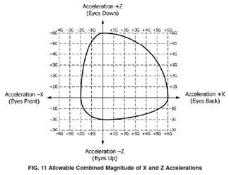
ASTM F2291 allows up to 6 g when a seated rider decelerates in the +X direction, which is how most zipline riders are braked (Figure 4). In practice, a rider braked at 6 g swings up and can hit the cable. The manufacturer of the zipSTOP therefore advises against braking scenarios above 2.5 g, for comfort and to limit swing-up; this limit sets the minimum braking distance in the zipSTOP stop-distance charts.

Seated rider with the X, Y and Z acceleration axes used in ASTM F2291

Figure 4 — Acceleration axes of a seated rider. Zipline braking is mostly in the +X direction.

ASTM F2291 chart of allowable sustained acceleration limits for a seated rider

Figure 5 — Allowable acceleration envelope from ASTM F2291.

🪢

A prusik knot backup

The primary brake fails at 60 km/h. If a prusik knot works at all, a rough estimate is that it stops the rider within 0.5 m: that is 28.3 g, nearly five times the ASTM limit. Even over a full metre it is still 14 g.

🔩

A cable clamp as a stop

A rigid stop such as a cable clamp brakes the rider in an even shorter distance than a prusik knot. The g-loads become higher still. This is not an emergency arrest device.

📏

A real EAD

An emergency arrest device gives the rider enough braking distance to stay within safe g-loads at the highest arrival speed, and engages without input from rider or guide.

These figures are simplified, best-case calculations: they assume constant deceleration over the whole braking distance. Reality differs. A spring pack, for example, brakes harder as its springs compress, which gives higher peak g-loads than calculated. On the other hand, the rider is not rigidly attached to the trolley and can swing, which lengthens the braking distance. Theory gives a baseline; real-world testing with purpose-built equipment by a competent designer or engineer is the preferred way to verify an EAD. ASTM F2137 describes how to measure the dynamic characteristics of rides and devices.

Testing

How to test a primary brake and an emergency arrest device

The standards do not prescribe a type or brand of emergency brake. Every installation is different, and it is the responsibility of the builder, installer and operator to make sure the primary brake is installed and operated to the applicable standard and the manufacturer's manual — with an adequate EAD.

What the standards ask for

Under ACCT, a qualified person designs the test methods, oversees the tests and assesses the results. The tests must prove:

✓
How the brake system performs at the extremes of the design range for rider weight and arrival speed
✓
That the brake system performs reliably and as designed

The emergency brake is part of the brake system, so it is tested too when a primary-brake failure could lead to an arrival above 10 km/h (6 mph) or to harmful contact with terrain, objects or people in the landing area. ASTM F1193 adds performance testing: a series of tests that show the installed ride conforms to its design criteria. Because one of those criteria is that the brake system is fail-safe, that has to be proven as well.

How to test the EAD in practice

  • Disconnect the primary brake.
  • Send a range of unmanned test weights down the line, from the lightest to the heaviest rider.
  • Measure the arrival speed of each run, for example with a radar speed gun or timing gates.
  • Watch how each weight is stopped by the EAD: would a rider be seriously hurt? If so, the device is not an emergency arrest device.
  • Reconnect the primary brake and repeat the test series for the full brake system.
Cold, wet conditions and strong winds can raise arrival speeds considerably. Take them into account in the tests, and make sure the primary brake and the EAD can handle the worst case.

Compare end brakes on our zipline brake systems page. Ordering parts for an existing line? See the shop categories for zipline braking systems, zipline trolleys and zipline harnesses.

Frequently asked questions

What is a zipline braking system?

The combination of a primary brake, which stops every rider, and an independent emergency arrest device, which stops the rider automatically if the primary brake fails. Spring brakes, magnetic end brakes such as zipSTOP and block-and-tackle systems are common primary brakes.

Does every zipline need an emergency brake?

The ACCT standards require an emergency brake where a primary-brake failure could mean an arrival above 10 km/h (6 mph) or harmful contact in the landing area, and ASTM requires the brake system to be fail-safe. The manufacturer of zipSTOP requires an EAD on every line that uses its brakes. Read more in does your zipline need an emergency arrest device?

What is the landing zone of a zipline?

The landing zone is the stretch at the end of the line where riders are slowed down, stopped and unclipped. It includes the braking distance of the primary brake and the EAD, clearance around the rider and a safe position for staff. See the landing zone checklist in the parts of a zipline.

How many g can a zipline rider take?

ASTM F2291 allows up to 6 g for a seated rider braked in the +X direction. For comfort and to limit swing-up, the manufacturer of zipSTOP advises staying below 2.5 g with its brakes. The braking distance needed for that follows from the arrival speed.

Related content
Zipline design packages
From a 5–10 day feasibility study to the Construction Book and certification support. Fixed fee per package, the study fee credited back when we build.
✓ Adventure park builder since 2005✓ Ziplines designed to EN 15567✓ Speed simulation for the full rider weight range✓ Offices in Ede, Amsterdam, Dubai and Riyadh

Is your braking system designed for the worst case?

Whether you plan a new zipline or want to upgrade the brakes on an existing one, we look at arrival speeds, braking distances and the emergency arrest device as one system.